DOOH Advertising
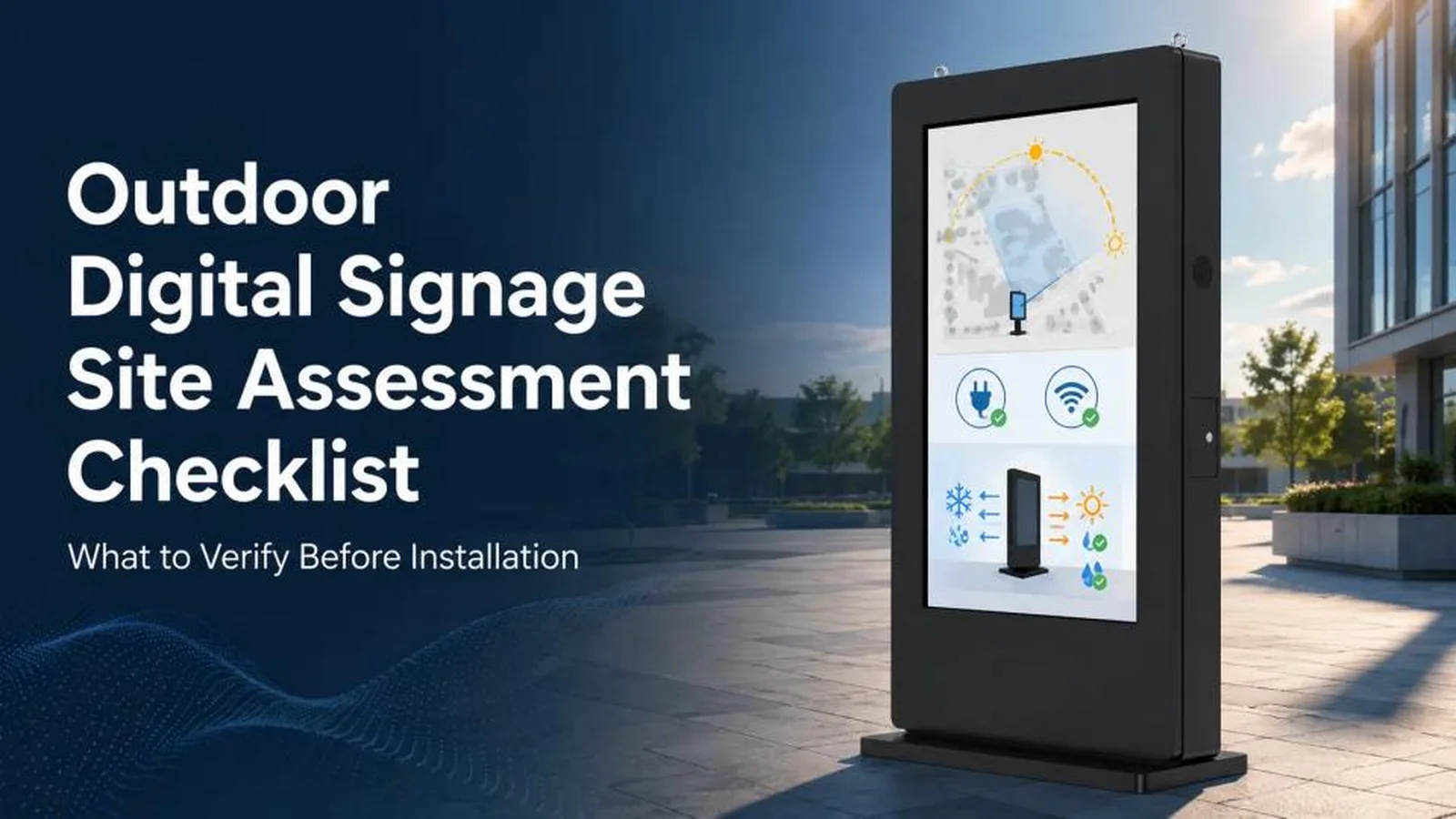
Outdoor Digital Signage Site Assessment Checklist: What to Verify Before Installation
Outdoor digital signage projects can fail long before installation because of glare, wind, weak foundations, inadequate power, poor connectivity or limited service access. This practical checklist helps integrators and buyers evaluate a site, identify risks and match display specifications to real-world conditions.
August 19, 2026
 ChatGPT
 Grok
Grok Perplexity
 Claude
Outdoor digital signage projects rarely fail because someone forgot to order a screen. More often, problems begin much earlier: the display faces harsh afternoon sun, the mounting structure cannot support the wind load, network coverage is weaker than expected, or maintenance access was never considered.
A site assessment connects the proposed display specification with the conditions it will face every day. It gives integrators, network operators and property owners the information needed to select suitable hardware, plan infrastructure and identify risks before installation begins.
The following framework covers eight areas that should be documented before an outdoor display is purchased or installed.
1. Start with the operating environment
Regional weather data is useful, but it does not fully describe a particular installation point. A screen beside a reflective glass facade may experience far more solar heat than one a few blocks away. A coastal site may face salt spray, while a nearby enclosed courtyard does not.
The survey should record:
- Direct sunlight and shadow patterns throughout the day
- Seasonal temperature extremes at the site
- Humidity, rainfall, snow, ice and hail exposure
- Dust, sand, industrial pollutants or salt spray
- Reflections from glass, water or polished surfaces
- Prevailing wind direction and design wind speeds
- Flooding, drainage and standing-water risks
Sunlight affects more than readability. Solar loading can raise internal temperatures and increase the cooling demand on the enclosure. Brightness, anti-reflective treatment, optical bonding and thermal management therefore need to be evaluated as a system—not as isolated specifications.
Site conditions also influence the required ingress and corrosion protection. An IP rating should be matched to the actual exposure, enclosure design and installation method. The IEC 60529 IP Code classifies the protection provided by electrical enclosures against dust and liquids; it does not replace a project-specific review of drainage, seals, condensation and corrosion. An IP65 outdoor display may be appropriate for one installation and insufficient for another. Laboratory tests provide a repeatable way to verify field findings: IEC 60068-2-2 (dry heat), ISO 9227 (salt spray) and ASTM G154 or ISO 4892 (UV weathering) are common references for judging enclosure and coating performance before the design is frozen.
2. Verify the structure and mounting method
An outdoor display must withstand its own weight as well as wind, vibration and accidental impact throughout its service life. The survey should identify the mounting substrate and establish whether it can safely accept the proposed load.
For wall-mounted displays, document the wall material, thickness, condition and location of structural elements. Decorative cladding or nonstructural veneers should not be assumed to provide adequate support. Existing cracks, corrosion, water damage or spalling may require further investigation.
For freestanding kiosks, assess the ground surface, drainage, slope and below-ground conditions. Foundation dimensions and reinforcement should be determined by a qualified engineer using the equipment weight, overturning moment, local soil conditions and applicable wind or seismic requirements. Wind and seismic design loads should follow the code in force at the site—ASCE 7-22 in the United States and EN 1991-1-4 in Europe are two common references. A single foundation detail should not be reused across every site.
Pole-mounted projects require confirmation that the pole and its foundation were designed for the additional projected area and wind load. Before drilling or excavation begins, underground utilities and embedded services should be located using the procedures required by the local authority.
3. Treat power as part of the display system
The electrical requirement includes more than the LCD panel. Cooling or heating equipment, the media player, networking hardware, touch components, sensors and other peripherals all contribute to total consumption.
A power assessment should confirm:
- Available voltage, frequency, phase and circuit capacity
- Distance from the electrical source to the display
- Estimated operating load and startup current
- Cable and conduit routes
- Grounding and surge protection requirements
- Voltage stability and local power-quality issues
- The need for a UPS, controlled shutdown or generator support
Electrical design, cable sizing, burial depth and protection devices must follow local code and be completed by qualified personnel. For essential messaging or wayfinding, the operator should also define what the screen must do during a power interruption.
Solar-powered installations need a separate energy study based on actual load profiles, local solar resource, seasonal conditions, battery autonomy and system losses. Display brightness and operating hours often have a major effect on system size.
4. Test connectivity at the exact location
Content delivery, device monitoring and remote diagnostics depend on reliable connectivity. A network plan based only on a coverage map or a quick phone test can overlook interference, weak signal quality and changes caused by the final enclosure.
For wired networks, measure the complete route and decide whether copper, fiber or an extender architecture is appropriate. Standard Ethernet over copper has distance limits (100 m per IEEE 802.3), while fiber may be preferable for long runs or electrically noisy environments.
For cellular or Wi-Fi connections, test signal strength and quality at the proposed mounting position using appropriate equipment. Nearby metal structures, power infrastructure and other transmitters can affect performance. Antenna placement should be evaluated before the enclosure design is finalized.
The survey should also address network segmentation, firewall and CMS requirements, secure remote access, local content caching and redundant connectivity for critical applications.
5. Measure visibility, not just foot traffic
A high-traffic location is not automatically a good display location. The screen must sit within the audience's natural field of view, at a suitable distance and angle, for enough time to communicate the message.
Record primary viewing distances, approach directions, audience speed, dwell zones and likely obstructions. Vehicle-facing signage generally requires larger type and simpler content than a pedestrian kiosk. Interactive displays need sufficient clear space and a mounting height that supports accessible use. In the United States, the 2010 ADA Standards for Accessible Design provide a reference point for accessible routes and operable parts; local requirements may differ.
Ambient light measurements should be taken at representative times, including the most demanding daylight period. Luminance is measured in nits (cd/m²); direct-sun exposure typically pushes the requirement far above an indoor specification, but the correct value still depends on the whole optical system. The display specification depends on incident light, reflections, cover-glass treatment, optical stack, contrast performance and viewing angle. High brightness alone cannot compensate for a highly reflective front surface or poor orientation.
Nighttime conditions matter as well. Automatic brightness control can improve comfort, reduce light spill and lower power consumption. Local rules may also limit nighttime luminance or changes in content.
6. Identify permits and compliance requirements early
Permitting can affect the schedule as much as manufacturing and shipping. Requirements vary by jurisdiction and may cover the sign itself, structural work, electrical installation, excavation, use of public space and traffic control.
Depending on the project, the assessment may need to address:
- Planning, zoning and sign permits
- Structural and electrical approvals
- Maximum sign area, height and luminance
- Historic district or design review
- Pedestrian clearance and emergency egress
- Accessibility requirements for interactive interfaces
- Product safety, EMC and environmental compliance
- Light pollution, audio and operating-hour restrictions
- Public right-of-way or encroachment permits
Applicable standards should be confirmed with local authorities and qualified professionals. Requirements such as NEC, BS 7671, CE marking or accessibility rules apply differently depending on location, equipment and use case. Product-specific references are worth naming in the project record: in North America, electric signs are commonly covered by UL 48 and EMC by FCC Part 15; in Europe, product safety often follows IEC 62368-1 with EMC under EN 55032 and EN 55035.
7. Plan for security and accidental damage
Outdoor displays can be exposed to tampering, vandalism, theft and vehicle impact. Review nighttime lighting, nearby surveillance, public access and local incident history. Potential measures include impact-resistant cover glass, tamper-resistant fasteners, protected locks, internal hinges and monitored access panels.
Where vehicles can approach the installation, bollards or another engineered barrier may be appropriate. Flood levels, falling branches, snow or ice shedding, nearby construction and seismic conditions can also influence placement and mechanical design.
8. Design for installation and service access
A display may fit at the final mounting point but still be impossible to deliver safely. The survey team should trace the complete route from unloading to installation and record gate widths, doorways, turning space, overhead clearance, surface loading limits and crane or lift access.
The plan should identify a secure staging area, temporary traffic controls, weather protection during installation, packaging removal and safe technician access after commissioning. Clearance is also required for doors, filters, fans and replaceable components.
Maintenance access is often overlooked during aesthetic review. If routine service requires closing a lane, removing landscaping or hiring a crane, the total cost of ownership can rise substantially.
What the site report should contain
A useful report should allow engineering, installation and operations teams to work from the same verified information. It should begin with the location, including the address, GPS coordinates, proposed orientation and annotated photographs from the main audience approaches.
The environment section should document the sun path, temperature range, precipitation, wind exposure and contaminants such as dust, sand or salt spray. The structure section should describe the mounting substrate, proposed installation method, load data and any structural engineering review that is required.
The power section should record the supply characteristics, cable route, available capacity, protection requirements and backup-power needs. The data section should include connection options, on-site signal test results, cable lengths, network security requirements and any local content or offline-playback plan.
The audience section should summarize viewing distance, approach direction, traffic speed, dwell time, likely obstructions and accessibility considerations. The compliance section should list permits, applicable codes, approvals and operating restrictions.
The report should also cover logistics, including the delivery route, lifting access, staging area and traffic control. The service section should explain technician access clearances, maintenance procedures and the replacement strategy. Finally, the risk section should record each identified hazard, its likely consequence, the mitigation action and the person responsible for follow-up.
Photographs should show the display position from multiple audience approaches, the surrounding environment, mounting surface, power and data entry points, and installation access route. Measurements and assumptions should be labeled rather than left for the next team to interpret.
Five mistakes that repeatedly cause problems—and how to avoid them
- Using regional averages instead of site-specific conditions. Local reflections, wind channels, shade and contaminants can change requirements significantly. Fix: walk the actual mounting point and measure the microclimate there, not at a weather station a few blocks away.
- Selecting brightness without evaluating the optical system. Readability depends on contrast and reflection control as well as luminance. Fix: measure ambient light at the worst daylight hour and evaluate cover glass, contrast and orientation together.
- Treating the foundation as a standard accessory. Wind, soil and seismic conditions must inform the structural design. Fix: have a qualified engineer size the foundation from site-specific data.
- Assuming wireless connectivity will be reliable. Performance needs to be tested at the installation point and planned with the finished enclosure in mind. Fix: test at the mounting position and plan a wired fallback where the signal is marginal.
- Forgetting future maintenance. A difficult filter change or inaccessible electronics bay creates recurring cost and longer outages. Fix: confirm filter, fan and component access routes—and any crane or lift needs—before the design is approved.
Turning site data into the right specification
The value of a site survey lies in how its findings change the system design. Strong solar exposure may call for a brighter panel, lower-reflection cover glass and additional thermal capacity. Coastal air may require upgraded coatings and corrosion-resistant hardware. Weak cellular coverage may change the antenna position or justify a wired connection. Limited rear clearance may favor front-serviceable equipment. Documented site data also supports warranty discussions, insurance reviews and any later relocation of the display.
Manufacturers and shortlisted outdoor digital signage suppliers should receive the site report before the final configuration is approved. For buyers comparing outdoor LCD display manufacturers, the key question is whether a supplier can translate site conditions into a documented system recommendation.
Frequently asked questions
What should be checked before installing outdoor digital signage? Check the site environment, mounting structure, power supply, network connection, audience visibility, permits, security risks, delivery route and future maintenance access. The assessment should document measurements, photographs, assumptions and the person responsible for each mitigation action.
How bright should an outdoor digital signage display be? There is no single brightness value for every site. The specification should be based on measured ambient light, direct sun exposure, viewing distance, reflections, cover-glass treatment, contrast and nighttime operating rules. A high-brightness panel cannot solve poor orientation or excessive front-surface reflection by itself.
What IP rating is suitable for an outdoor display? The required rating depends on rain, water-jet exposure, dust, drainage, cleaning methods and the enclosure's complete sealing design. IP ratings are defined under IEC 60529, but the rating should be reviewed together with condensation control, corrosion protection and the installation method.
Do outdoor digital signage projects require a site survey? For permanent or high-value installations, a site survey is strongly recommended. It can reveal structural, electrical, network and access constraints before hardware is ordered, reducing redesign, installation delays and future service costs.
What should buyers ask outdoor digital signage suppliers? Ask suppliers how they evaluate sunlight and thermal load, what structural information they need, how they validate IP and impact protection, what connectivity options are supported, how service access is handled and which documents are supplied for local approval. A supplier should be able to explain how its recommendation follows from the site data.
Conclusion
A successful outdoor digital signage installation begins with verified site data—not a product datasheet. Evaluating the environment, structure, utilities, audience, regulations, security and service access before procurement reduces redesign, shortens installation time and supports more reliable operation.
This framework should be treated as a shared project record. When the consultant, integrator, manufacturer, installer and operator are working from the same measurements and assumptions, the display is far more likely to perform as intended long after commissioning.
About the author
David Peng writes for MWE (Marvel Technology), an outdoor LCD display manufacturerand outdoor digital signage supplier specializing in high-brightness LCD displays, weather-resistant kiosks and customized commercial display systems. The MWE engineering team's most useful project inputs include the expected temperature range, sunlight exposure, mounting method, local power supply, connectivity plan and service-access constraints. Providing those details early helps its engineers evaluate a high-brightness outdoor LCD display, enclosure, thermal management and installation options against the real operating environme
Included In This Story

MARVEL TECH GROUP CO., LTD.
Make Win Easy
MWE manufactures commercial-grade LCD/LED digital signage for retail, QSR, and DOOH applications. Specializing in IP65-rated outdoor displays (2500-5000 nits), indoor video walls, LED poster displays, and Android-based solutions. Regional stock in USA/Germany. Tier-1 components (Samsung, LG, BOE). Built for reliability.
Related Media
Subscribe
Get the latest news and resources from Digital Signage Today.